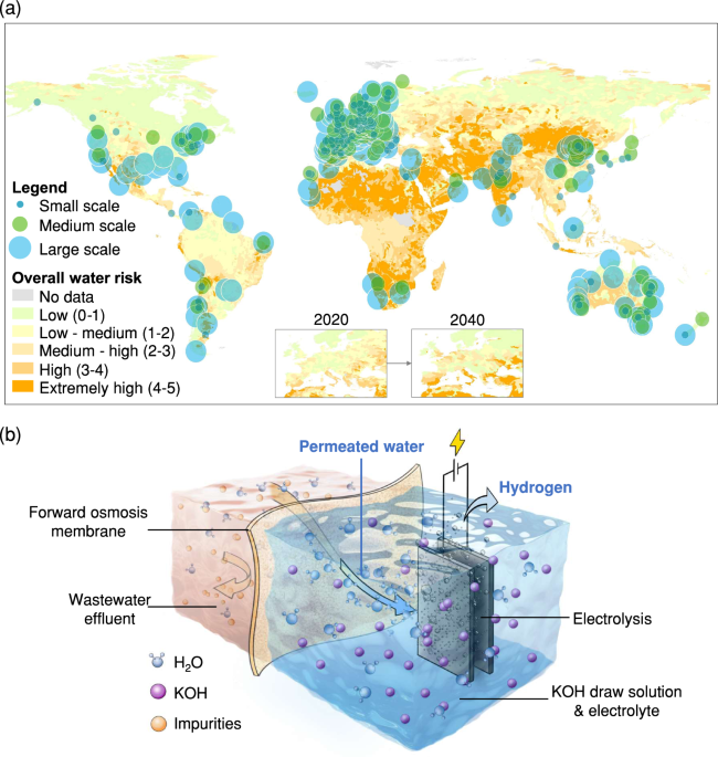
Producing clean water via FO using KOH as a draw solution
To integrate FO with AWE, KOH and two other electrolytes including sodium bicarbonate (NaHCO3), and potassium pyrophosphate (K4P2O7) were considered as potential draw solutions for FO instead of the conventional NaCl, as NaCl induces a CER, which negatively affects H2 generation and damages both the FO membrane and electrodes30,31,32,33. Among these electrolytes at a concentration of 1 M, KOH shows current densities 18 and 12 times higher than those of NaHCO3 and K4P2O7 at 2 V, respectively (Supplementary Fig. 1). The higher current density of KOH represents a higher H2 production rate in AWE compared to the other two electrolytes. To not compromise the AWE performance, we tested if KOH could be used as the draw solution in FO for extracting water from simulated wastewater effluent containing sodium acetate (NaAc), ammonia/ammonium ions (NH3/NH4+), and chloride. Besides, although the current density of KOH increases with increasing concentration34, KOH at concentrations higher than 1 M causes the pH of the draw solution to exceed 14, which carries the risk of damaging commercial TFC-FO membranes. Therefore, we tested 1 M KOH to evaluate its impact on the TFC-FO membranes (details given in the Methods section).
Figure 2a shows the water flux (i.e. the permeated water volume per unit of time and per unit of membrane areas, L h–1 m–2 (LHM)) and reverse salt flux (RSF) (i.e. draw solute permeated to the feed solution side per unit of time and per unit of membrane areas, g h–1 m–2 (GHM)) of the FO process using 1 M KOH as the draw solution for five cycles of five hours each. The water flux decreased from 17.2 ± 0.3 to 14.9 ± 0.1 LHM after 5 h in each cycle, while the RSF remained constant at ~121 ± 3 GHM. The water flux is comparable to a system using NaCl as a draw solution (Supplementary Fig. 2), indicating that the KOH is an effective draw solution to extract water through FO processes. The primary concern associated with the use of KOH as a draw solution is its potential to damage the FO membrane, as the reverse flux of KOH may cause hydrolysis of the polymer chains that constitute the membrane selective layer (on the feed side)35. The integrity of the commercial TFC-FO membrane after operating in 1 M KOH solution was examined by comparing the water flux and RSF of the used membrane after the tests shown in Fig. 2a and a new pristine membrane, both using deionised water as the feed solution and 1 M NaCl as the draw solution (Fig. 2b). Figure 2b shows that the water flux of the used membrane was reduced by less than 5% compared to the pristine membrane, while the RSF of the two membranes was comparable. The membrane integrity in terms of water flux and RSF was not compromised. In addition, results from scanning electron microscopy (SEM) revealed no change in the “leaf-like” surface of the selective layer on the unused membrane and the used membrane after five cycles (Fig. 2c, d and Supplementary Fig. 3a, b) and in the peaks of the functional groups in the Fourier transform infra-red spectroscopy (FTIR) (Supplementary Fig. 4). The comparable water flux and RSF between the pristine and the used membrane suggest that the FO membrane was not damaged by KOH. The high RSF may be attributed to the smaller hydrated ionic size and higher ionic mobility of KOH36, or the ionisation of the membrane via deprotonation of the functional groups on its surfaces facilitating the transport of cations across the membrane37,38. Nonetheless, the RSF accounted for less than 1.5% of the initial KOH concentration after a cycle, suggesting the impact due to this issue was minor. Moreover, since KOH is inexpensive, any losses can be easily replenished in the system.

a Water flux (Jw) and reverse salt flux (RSF) of the FO process with simulated wastewater effluent containing sodium acetate, NH3/NH4+, and chloride as feed solution and 1 M KOH as draw solution for five cycles. The dashed lines represent five cycles of 5 h each. (Conditions: [NaAc] = 7.5 mM, [NH3/NH4+] = 2.2 mM as N, [Cl–] = 4.2 mM, and flow rate = 70 ml min–1); b comparison in water flux (Jw) and RSF between the pristine membrane and the 5-cycle used membrane using deionised water as feed solution and 1 M NaCl as draw solution. The inset figure shows the reverse salt flux from the two membranes (error bars represent standard deviation from two independent replicates); c SEM images showing the surface morphology of the selective layer on the pristine membranes; d SEM images showing the surface morphology of the selective layer on the 5-cycle used membrane; e the rejection of sodium acetate, ammonia, and chloride by the FO membrane using 1 M KOH as draw solution (conditions: [Sodium acetate] = 7.5 mM, [Ammonia] = 2.2 mM as N, [Chloride] = 4.2 mM, and flow rate = 70 ml min–1); f J–V curves for 1 M KOH and 1 M KOH mixed with different impurities including sodium acetate, ammonia, and chloride (error bars represent standard deviation from three independent replicates). Source data are provided as a Source Data file.
Since impurities in the wastewater effluent may permeate through the FO membrane and thus affect electrolysis, we examined the rejection of common impurities in the wastewater effluent by the FO membrane, including NaAc, NH3/NH4+, and chloride (Fig. 2e). The rejection rates of NaAc, NH3/NH4+, and chloride remained stable throughout the five cycles at about 85%, 63%, and 98%, respectively. The lower rejection of NH3/NH4+ occurred as the TFC-FO membrane surface is negatively charged, which allows anions to be intercepted more readily than cations or unionised NH3 which is the dominant form of NH3/NH4+ at high pH. The rejection of additional common impurities found in wastewater and varied pH levels was also examined, with rejection rates exceeding 90% (Supplementary Figs. 5 and 6). The potential impacts to the electrolysis process from the permeated impurities were then investigated using a commercial 5-cell alkaline stack with nickel alloy-based electrodes by comparing the current density–voltage (J–V) curves generated from: (i) 1 M KOH, (ii‒iv) 1 M KOH mixed separately with NaAc, NH3/NH4+, and chloride at a concentration of 10 mM for studying their accumulation effect, respectively, or (v) a 1 M KOH mixture consisting of 1.1 mM of NaAc, 0.7 mM NH3/NH4+ as N, and 0.08 mM chloride observed in the permeate from the rejection test, as shown in Fig. 2f. All tested solutions exhibited a consistent behaviour in their J–V curve performances, suggesting that the presence of NaAc, NH3/NH4+, and chloride in KOH minimally impacted the current densities. We infer that the high concentration of KOH, sustaining a high pH (>8), mitigated the negative effects of NaAc and NH3/NH4+ and suppressed side reactions such as chlorine evolution31,39. Therefore, the above results of the high and constant water flux, the intact FO membrane, and the minor impact of impurities permeated from the FO membranes on electrolysis suggested using KOH as the draw solution in the FO process to extract water from wastewater effluent is feasible.
Integrating FO with AWE
A water-hydrogen balance model was established to quantify and balance the FO and AWE units in the FOWSAWE system, as shown in Fig. 3a, with the objective of continuous operation to effectively produce H2 from wastewater effluent. In the integrated system, clean water is first extracted from the wastewater effluent by the FO process using KOH as the draw solution and then split into H2 and oxygen (O2) by AWE using the 5-cell alkaline stack containing nickel alloy powder combined with nickel foam electrodes separated by polymer diaphragms (detailed setup is shown in the ‘Methods’ section). A sustainable operation of this system thus requires a dynamic equilibrium that enables the water production rate crossing the FO membrane (QFO) to match the water rate consumed by AWE (QAWE) as shown in Eq. 1, while maintaining a consistent concentration of KOH.
$${{Q}_{{{{{{\rm{FO}}}}}}}\,=\,S\Delta C\frac{{K}_{{{{{\rm{W}}}}}}I}{d}{{RT}}\,=\,Q}_{{{{{{\rm{AWE}}}}}}}\,=\,{i}_{{{{{{\rm{cell}}}}}}}\frac{{{{{{\rm{FE}}}}}} \, {{{\cdot} \, N}_{{{{{{\rm{cell}}}}}}}V}_{{{{{\rm{m}}}}}}}{2F}$$
(1)
QFO is a function of controllable parameters in the FO process including the membrane area (S, cm2) and the concentration gradient between draw solution and feed solution (ΔC, M)40. The membrane permeability coefficient (Kw, L atm–1 s–1 cm–1), when multiplied by the van’t Hoff factor of the feed solution (I), represents how easily water can be extracted through the membrane, remaining constant throughout the test. Other parameters, including the membrane thickness (d = 0.1 mm), the ideal gas constant (R = 0.0821 L atm K–1 mol–1), and temperature (T = 296 K), also remained constant during the test. QAWE is only controlled by the applied current of AWE (icell, A)41, as other parameters, including the Faradaic efficiency (FE), the number of cells constituting the electrolyser stack (Ncell = 5 for our setup), Vm (as the molar volume of H2O at 0.018 L mol–1 at 296 K of T and 1 atm), and Faraday’s constant (F = 96,485 C mol–1) are constant throughout the test. Therefore, through balancing QFO and QAWE, a linear correlation was established to describe the specific normalised current of the FOWSAWE system (Ji, A cm−2), which is defined as the required current of this integrated system for handling the permeated water per area of FO membranes (icell S–1), changed with ΔC as shown in Eq. 2.
$${J}_{i}\,=\,\frac{{i}_{{{{{{\rm{cell}}}}}}}}{S}\,=\,\left(\frac{{K}_{{{{{\rm{w}}}}}}{\it{I}}}{d}{RT}\frac{2F}{{{{{{{{\rm{F}}}}}} \, {{{{{\rm{E}}}}}}\,N}}_{{{{{{\rm{cell}}}}}}}{V}_{{{{{\rm{m}}}}}}}\right)\Delta C\,=\,\varPhi \cdot \Delta C$$
(2)
where Φ is the H2 production potential (L A mol–1 cm–2), determined by the configurations of the FO membranes and AWE, types of feed and draw solutions, and operational conditions. H2 production potential (Φ) was calculated by substituting the values of Kw × I, d, R, T, FE, Ncell, and Vm into Eq. 2, and Kw × I was obtained experimentally by measuring QFO under given conditions of S and ΔC in an independent FO module using Eq. 1, whereas FE was calculated by measuring the H2 production rate and purity at a given icell of the AWE module (detailed in the ‘Methods’ section). In this study, Φ values for feeding deionised water and the wastewater effluent collected from a wastewater treatment plant in Hong Kong (HK-WWE1) to the FOWSAWE system were calculated as 1.55 and 0.95 A mol–1 cm–2, respectively. The lower Φ for wastewater effluent was attributed to impurities in the wastewater effluent reducing Kw × I. The obtained Φ values were then used to generate the relationship between Ji and ΔC when reaching a dynamic equilibrium for the FO and AWE units in the FOWSAWE system, as shown in Fig. 3b. Therefore, to maintain ΔC at 1 M, Ji was calculated as 1.55 and 0.95 A cm–2 for deionised water and HK-WWE1, respectively21.

a Schematics showing a dynamic equilibrium to balance the water production rate crossing the FO membrane (QFO) and the water consumption rate by AWE (QAWE) in the FOWSAWE system; b the specific normalised current (icell/S) as a function of the concentration gradient (ΔC) to reach the equilibrium in the FOWSAWE system fed with deionised water and wastewater effluent. Data can be reproduced using Eq. 2; c the water flux and ΔC of the FOWSAWE system during 2-cycle operation. The vertical dashed line represents the transition between the first cycle and second cycle; d the H2 production rate and H2 purity for using deionised water and wastewater effluent as the feed of the FOWSAWE system (error bars represent standard deviation from three independent replicates); e the resulting voltage during the operation of the FOWSAWE system. The vertical dashed line represents the transition between the first cycle and the second cycle (conditions: [KOH] = 1 M, S = 1 cm2, icell = 1.55 A for deionised water and 0.95 A for wastewater effluent (HK-WWE1)); f the water flux, voltage, and ΔC during the 168-h continuous operation of the integrated FOWSAWE system (conditions: [KOH] = 1 M, S = 1 cm2, and icell = 0.90 A using the HK-WWE-2). Source data are provided as a Source Data file.
The two setups of FO and AWE were then experimentally integrated using a 1 cm2 FO membrane and applying an icell of AWE of 1.55 and 0.95 A for deionised water and HK-WWE1 according to their Ji values, respectively (integrated process shown in Supplementary Fig. 17). As shown in Fig. 3c, d, the continuous operation of this integrated system over two cycles of 5 h each, demonstrated a stable water flux crossing the FO membrane, constant ΔC, and a stable H2 production rate when fed with either deionised water or secondary wastewater treated effluent. In addition, the molar ratio of the H2 generation rate to QFO was close to one after the two test cycles (Supplementary Fig. 7), indicating that nearly all the water produced from FO was consumed by AWE. These observations indicate a successful integration of FO and AWE processes and validate our established dynamic equilibrium for the FOWSAWE system. Using wastewater effluent as the feed resulted in a 38% decrease in both QFO and H2 production rate compared to feeding deionised water, which aligns with the decrease observed in the value of Kw × I from wastewater effluent. This indicates that these impurities mainly affect the capacity of the water produced from FO, and the ability of the FOWSAWE system to produce H2 relies on this water production capacity. Nevertheless, using wastewater effluent as the feed did not compromise the H2 purity, as evidenced by the comparable H2 percentage observed in samples produced using both deionised water and wastewater effluent, as shown in Fig. 3d. Additionally, the stability of H2 production was not affected either, as the FOWSAWE system operated at a near-constant voltage of 1.79 ± 0.01 V and maintained a Faradaic efficiency of over 99% throughout two cycles of 5 h each (Fig. 3e), indicating that there were no side reactions caused by impurities crossing the FO membranes or accumulation of undesired impurities.
A continuous 168-h operation of the FOWSAWE system was conducted to assess its long-term stability under consistent conditions using a wastewater effluent sample collected from a second wastewater treatment plant in Hong Kong (HK-WWE2), and the result is shown in Fig. 3f. The water flux decreased by ~12% from 15.6 to 13.7 LHM, whereas the voltage increased by 4% during the initial 24 h, starting from 1.75 V and maintaining at 1.82 V. In addition, the system sustained a ΔC consistently at around 1 M during the entire 168-h testing period. The 12% reduced water flux after the long-term operation was attributed to fouling from organic matter in the wastewater42, because the ratio of C to O elements on the membrane surface was reduced by ~13%, and no degradation of integrity for both the selective and support layers of the FO membrane was observed in SEM coupled with Energy Dispersive X-ray (Supplementary Table 3 and Fig. 8, respectively). FO membrane fouling was shown to be largely reversible, unlike the often irreversible fouling challenges faced in RO43, which means that the reduced water flux in our system can be easily recovered by backwashing or chemical washing. Notably, the H2 gas purity remained stably high at over 99% throughout the entire long-term operation (Supplementary Fig. 9). These results demonstrated the operational stability of the FOWSAWE system throughout the 168-h testing period. In addition, as the FOWSAWE system relies on the water flux to generate H2, we tested more wastewater samples from the southern and northeastern regions of China, with their composition and concentrations detailed in Supplementary Table 4. The results show that our system exhibited a constant water flux, voltage, and ΔC for various impurities and pH values from different wastewater samples (Supplementary Figs. 10–12). Despite the varied Kw × I caused by different impurities, the resulting H2 production rates were consistent and remained within a range of 5% (Supplementary Fig. 11d). These results validate the stability and adaptability of our system for producing H2 under varying wastewater conditions.
H2 production and energy efficiency of the FOWSAWE system
The H2 production and energy efficiency of the FOWSAWE system showed superior performance compared with two other membrane-based P2H systems for seawater purification integrated with electrolytic water splitting: (i) the seawater electrolysis system (SES) using hydrophobic PTFE membranes with 30% KOH as a self-dampening electrolyte (SDE), and (ii) the FOWS employing cellulose triacetate (CTA) membranes with 0.8 M sodium phosphate as the electrolyte21,22. The H2 produced in the three systems was compared by normalising the H2 production rate over the area of water-producing membranes, as shown in Fig. 4a. The FOWSAWE system produced the highest H2 rate at 448 Nm3 day–1 m−2 of TFC-FO membrane, which is 102 and 14 times higher than those of SES and FOWS, respectively. This significant improvement in H2 production compared with SES is primarily due to the higher Φ provided by FO membranes in producing more water. Unlike SES using hydrophobic PTFE membranes, the TFC-FO membrane is hydrophilic and thus offers higher Kw to allow water to permeate. This is verified by the 23‒32 times higher Ji of the TFC-FO membrane to reach equilibrium than the PTFE membrane at the same values of S, ΔC, and using identical AWE setups (Supplementary Fig. 13). Besides, PTFE membranes face wetting issues during operation, which reduces the ability to reject impurities as water penetrates the pores44,45. The enhanced H2 production compared to FOWS is mainly attributed to the 5× higher ΔC between wastewater effluent and 1 M KOH compared to the 0.2 M ΔC between seawater and 0.8 M sodium phosphate, enhancing the driving force for producing water. The H2 flux comparison along with the water-hydrogen model suggests the water production rate dominates in determining the H2 flux in a membrane-electrolysis system, highlighting the importance of optimising both the membrane type and the feed water source. Moreover, high water production rates offer additional benefits of requiring fewer membranes and associated equipment, thereby reducing space and capital costs which are particularly important considerations for scaling up the system.

a The comparison in H2 flux among three membrane-based P2H systems (error bar represents the standard deviation from three independent replicates); b the comparison in specific energy consumption (SEC) among three membrane-based P2H systems. The orange region represents the SEC range typical for direct wastewater electrolysis. The green region represents the SEC range for industrial alkaline water electrolysis; c H2 flux and SEC of the FOWSAWE system changed with KOH temperatures. Source data are provided as a Source Data file.
The FOWSAWE system exhibits low energy consumption, as shown in Fig. 4b, where the SEC of the three systems is compared in addition to direct wastewater electrolysis. The FOWSAWE system requires the lowest SEC at 4.43 kWh Nm–3 at an icell of 0.95 A using wastewater effluent as feed. This SEC is comparable to commercial alkaline electrolysis systems that use deionised water and is 10%, 34%, and 84% lower than SES, FOWS, and direct electrolysis of wastewater, respectively46. The lower SEC highlights the importance of preventing undesired impurities from electrolysis and using a pH-tolerant membrane to enable the use of KOH as an electrolyte as it has higher ionic conductivity for more efficient electron transfer. Such excellent energy efficiency is also applicable to other commercial AWE configurations, if the applied current matches the water-hydrogen equilibrium, making the FOWSAWE system easily adaptable and scalable to meet varying market demands. Therefore, the hydrophilic property of TFC-FO membranes, the higher ΔC resulting from wastewater effluent usage instead of seawater, and the use of an optimal electrolyte (i.e. KOH) all contribute to a high H2 flux and energy-efficient P2H conversion.
In addition, electrolysis is an exothermic process that generates heat, so capturing and utilising waste heat during AWE operations is critical in achieving the energy-efficient operation of the system. By simulating the capture and utilisation of the waste heat during AWE operations to heat up the KOH draw solute temperature to 40 °C, the FOWSAWE system shows an increase of H2 flux by 11% and a decrease of SEC from 4.43 to 3.96 kWh Nm–3 (Fig. 4c and detailed calculations provided in Supplementary Note 1). This brings us closer to the target of 3.75 kWh Nm–3 proposed by the International Renewable Energy Agency47. The enhanced H2 flux is mainly due to the increased water production at higher temperatures, indicated by Eq.148, while the reduced SEC is attributed to the increased KOH ionic conductivity reducing the overall resistance of the cell and enabling more efficient electron transfer (Supplementary Fig. 14). These results also suggest that the FOWSAWE system can perform better in hot regions where the wastewater has temperatures of up to 35 °C and can potentially heat the draw solutions during membrane operational processes28, or in areas with abundant solar energy that can be used for heating.
Implications for H2 production using wastewater effluent
This study demonstrated the use of municipal wastewater effluent by a FOWSAWE system for fast and energy-efficient green H2 generation to address the large-scale H2 production need associated with potential water constraints. The FOWSAWE system exhibits stable and continuous H2 production at the highest yields of H2 to date (448 Nm3 day–1 m–2) using alternative water resources achieving a high H2 purity of >99% and low SEC of 4.43 kWh m–3 during the entire testing period of over 10 h. In addition, the FOWSAWE system demonstrated long-term stability by being operated continuously for 168 h using real wastewater effluent and proved its capability and adaptability in producing H2 across diverse wastewater conditions found in different regions.
Using wastewater effluent is crucial for sustainable H2 production in regions where seawater is unavailable or freshwater resources are scarce, especially as H2 projects are rapidly expanding amid the foreseeable intensified worldwide water stress. The modular FO and AWE system along with the established water-hydrogen balance model allow the FOWSAWE system to operate with different influent water quality at different scales, ensuring an easy yet versatile approach for sustainable P2H conversion from the household to the city scale. The integration of TFC-FO with electrolysis can reduce the capital costs of water treatment by up to 46% compared to conventional RO and FO–RO processes49, providing a strong economic incentive for FOWSAWE adoption. Addressing pressing global challenges such as water scarcity, climate change, and energy insecurity requires urgent action. Existing technologies, such as the FO and AWE, can substantially impact on solving these challenges if applied and integrated more effectively. The FOWSAWE system exemplifies leveraging synergistic technologies to rapidly develop economical, efficient, and sustainable solutions for interconnected environmental issues.
In addition to the H2 production market for industrial use and energy storage, the FOWSAWE system provides advantages to wastewater treatment plants and many industries, as it serves as a tool for water reuse. The system has the potential to reduce the treatment load and wastewater discharge while simultaneously generating onsite energy, and mitigating environmental impacts50. It is estimated that an onsite FOWSAWE station with a capacity of 5‒6 MW can produce O2 at ~20,000 kg day–1, which can supply the aerobic processes of a wastewater treatment plant in treating 50,000 m3 day–1 of wastewater (calculation shown in Supplementary Note 2)51,52 or support high-density in-land and offshore aquaculture53,54. Moreover, fuel cells that use H2 to generate electricity also produce high-purity water as a byproduct, which can be supplied to industries that require it, e.g. semiconductor and pharmaceutical industries.